Selecting Carbon Fiber Components for Reinforcement

Selecting Carbon Fiber Components for Reinforcement

Step-by-step guide on how to assess the severity of foundation cracks and choose the appropriate repair method.

Overview of carbon fiber as a material and its benefits for structural reinforcement


Carbon fiber is a remarkable material that has gained significant attention in recent years due to its exceptional properties and versatility. Regular inspections help detect foundation problems early foundation repair service concrete. In the realm of structural reinforcement, carbon fiber has emerged as a game-changer, offering a multitude of benefits that make it an ideal choice for a wide range of applications.

At its core, carbon fiber is composed of thin, strong strands of carbon atoms bonded together to form a lightweight yet incredibly strong material. This unique composition gives carbon fiber its remarkable strength-to-weight ratio, making it an attractive option for applications where weight savings are crucial without compromising structural integrity.

One of the primary advantages of using carbon fiber for structural reinforcement is its exceptional tensile strength. Carbon fiber boasts a tensile strength that is several times greater than that of steel, allowing it to withstand immense loads and stresses without deforming or failing. This makes it an ideal material for reinforcing structures subjected to heavy loads, such as bridges, buildings, and infrastructure projects.

Furthermore, carbon fiber is renowned for its durability and resistance to corrosion. Unlike traditional materials like steel, which can rust and deteriorate over time, carbon fiber remains unaffected by environmental factors such as moisture, chemicals, and UV radiation. This inherent resistance to corrosion ensures that carbon fiber-reinforced structures maintain their strength and integrity for decades, reducing the need for frequent maintenance and repairs.

In addition to its strength and durability, carbon fiber offers excellent fatigue resistance. This means that structures reinforced with carbon fiber can withstand repeated loading and unloading cycles without experiencing significant degradation or failure. This is particularly important for applications where structures are subjected to dynamic loads, such as bridges and aerospace components, where fatigue failure can have catastrophic consequences.

Another key benefit of carbon fiber is its design flexibility. Carbon fiber can be molded into complex shapes and structures, allowing engineers and designers to create innovative and customized solutions tailored to specific reinforcement needs. This flexibility enables the integration of carbon fiber reinforcement into a wide range of applications, from small-scale repairs to large-scale infrastructure projects.

Moreover, carbon fiber is environmentally friendly compared to traditional materials like steel. Its lightweight nature reduces the overall weight of structures, leading to lower transportation costs and reduced carbon emissions during manufacturing and construction. Additionally, carbon fiber can be recycled and reused, minimizing waste and promoting sustainable practices in the construction industry.

In conclusion, carbon fiber offers a multitude of benefits for structural reinforcement. Its exceptional strength, durability, fatigue resistance, design flexibility, and environmental friendliness make it an ideal choice for a wide range of applications. As technology continues to advance and carbon fiber becomes more accessible, its use in structural reinforcement is poised to grow, revolutionizing the way we build and reinforce structures for the future.

Factors to consider when selecting carbon fiber components for residential foundation repair


When it comes to residential foundation repair, selecting the right carbon fiber components is crucial for ensuring both effectiveness and longevity. Here are several key factors to consider when making your choice:

Firstly, the structural integrity of the foundation is paramount. Carbon fiber components should be chosen based on their ability to provide the necessary strength and support to the compromised areas. This involves assessing the extent of the damage and determining the load-bearing requirements.

Secondly, compatibility with existing materials is essential. The carbon fiber components must be compatible with the type of foundation material, whether it be concrete, brick, or another substance. This ensures a seamless integration and optimal performance.

Thirdly, consider the environmental conditions the components will be exposed to. Factors such as moisture, temperature fluctuations, and potential chemical exposure can affect the durability of carbon fiber. Selecting components designed to withstand these conditions will enhance the longevity of the repair.

Fourthly, ease of installation is a practical consideration. The chosen carbon fiber components should be straightforward to install, minimizing labor costs and reducing the potential for errors during the repair process. This is particularly important for DIY enthusiasts or those looking to save on professional labor costs.

Fifthly, consider the manufacturer's reputation and warranties offered. Reputable manufacturers often provide warranties that can offer peace of mind and protection against unforeseen issues. This can be a significant factor in the overall value and reliability of the carbon fiber components.

Lastly, budget constraints should be taken into account. While it may be tempting to opt for the cheapest option, investing in high-quality carbon fiber components can lead to better long-term results and cost savings in the future.

In conclusion, selecting carbon fiber components for residential foundation repair involves a careful balance of structural requirements, material compatibility, environmental resilience, ease of installation, manufacturer reputation, and budget considerations. By thoughtfully evaluating these factors, homeowners can ensure a successful and durable foundation repair.

Common types of carbon fiber components used in foundation repair and their applications


When it comes to reinforcing foundations, carbon fiber components have become increasingly popular due to their strength, durability, and versatility. The use of carbon fiber in foundation repair offers numerous advantages over traditional materials, making it a preferred choice for many construction professionals. In this essay, we will explore the common types of carbon fiber components used in foundation repair and their specific applications.

One of the most widely used carbon fiber components in foundation repair is carbon fiber strips. These strips are typically made from high-strength carbon fibers embedded in an epoxy resin. They are applied to the surface of concrete foundations to provide additional tensile strength and prevent cracking. Carbon fiber strips are particularly effective in reinforcing foundations that are subject to settlement or shifting, as they can significantly enhance the structural integrity of the concrete.

Another common type of carbon fiber component used in foundation repair is carbon fiber fabric. This fabric is made from woven carbon fibers impregnated with an epoxy resin. It is applied to the surface of concrete foundations in a similar manner to carbon fiber strips but offers a more flexible and conformable reinforcement solution. Carbon fiber fabric is often used to wrap around columns, beams, and other structural elements to increase their load-bearing capacity and resistance to bending and shear forces.

In addition to strips and fabric, carbon fiber rods and bars are also commonly used in foundation repair. These components are made from bundles of carbon fibers encased in a protective coating, such as epoxy or polyethylene. Carbon fiber rods and bars are often used as internal reinforcement in concrete foundations, providing additional strength and stability to the structure. They are particularly useful in repairing foundations with deep cracks or voids, as they can be inserted into the concrete to bridge the gaps and restore the integrity of the foundation.

Furthermore, carbon fiber grids are another type of component that finds application in foundation repair. These grids consist of intersecting carbon fiber strands bonded together with an epoxy resin. They are applied to the surface of concrete foundations to provide a uniform and distributed reinforcement. Carbon fiber grids are effective in preventing the propagation of cracks and enhancing the overall durability of the foundation.

In conclusion, carbon fiber components play a crucial role in foundation repair due to their exceptional strength, durability, and versatility. Whether in the form of strips, fabric, rods, bars, or grids, these components offer reliable reinforcement solutions for a wide range of foundation issues. By selecting the appropriate carbon fiber components and applying them correctly, construction professionals can ensure the long-term stability and performance of reinforced foundations.

Installation techniques and best practices for carbon fiber reinforcement in residential settings


Certainly!

When it comes to reinforcing residential structures with carbon fiber, it's essential to not only select the right components but also employ optimal installation techniques and adhere to best practices. This ensures longevity, structural integrity, and safety.

Firstly, preparation is key. Before any installation, a thorough inspection of the area to be reinforced is necessary. This involves checking for any existing damage, moisture issues, or structural weaknesses. Addressing these beforehand ensures that the carbon fiber reinforcement will be effective.

Cleaning the surface where the carbon fiber will be applied is another critical step. Any dust, grease, or loose material must be removed to ensure proper adhesion. This might involve using a wire brush, vacuum, or even a mild detergent solution followed by a thorough rinse.

When it comes to applying the carbon fiber, it's imperative to use the correct adhesive. Most carbon fiber systems come with a recommended resin or epoxy. It's essential to mix this according to the manufacturer's instructions to ensure optimal bonding.

Application techniques vary depending on the specific product, but generally, the carbon fiber fabric is laid out on the prepared surface. The adhesive is then spread over the fabric, ensuring there are no air pockets or wrinkles. This might require the use of a squeegee or roller.

One of the best practices in carbon fiber reinforcement is to ensure even distribution and adequate coverage. This means the fabric should be completely saturated with the adhesive, but not to the point of dripping. Over-saturation can lead to weak bonds, while under-saturation might not provide the desired strength.

Curing time is another crucial factor. After application, the carbon fiber needs time to cure and bond properly. This duration can vary based on the product and environmental conditions, but it's essential to allow the recommended curing time before subjecting the area to any stress or load.

Lastly, always consider safety. When working with adhesives and carbon fiber, protective gear such as gloves, masks, and goggles should be worn. Proper ventilation is also crucial, especially when working indoors.

In conclusion, while selecting the right carbon fiber components is vital, employing the correct installation techniques and adhering to best practices ensures the longevity and effectiveness of the reinforcement in residential settings.

Case studies showcasing successful use of carbon fiber components in residential foundation repairs


When it comes to residential foundation repairs, the use of carbon fiber components has emerged as a highly effective and innovative solution. This advanced material, known for its remarkable strength-to-weight ratio and durability, has been successfully employed in numerous case studies across the globe. These real-world applications not only demonstrate the efficacy of carbon fiber but also highlight its advantages over traditional materials.

One notable case study involves a historic home in New England suffering from significant foundation settling. The homeowners were concerned about the structural integrity of the house and the potential damage to its historical features. Engineers opted for carbon fiber strips to reinforce the foundation. The carbon fiber components were installed along the perimeter of the foundation, providing additional support without the need for extensive excavation. The results were impressive: the settling was effectively halted, and the structural stability of the home was restored, all while preserving the home's historical charm.

In another instance, a modern suburban house faced issues with its foundation due to expansive soil conditions. Traditional repair methods would have been invasive and costly, involving extensive digging and replacement of sections of the foundation. Instead, carbon fiber wraps were applied to the affected areas. These wraps offered immediate reinforcement and were less intrusive than conventional methods. The homeowners were pleased with the quick installation process and the minimal disruption to their daily lives. Moreover, the long-term performance of the carbon fiber ensured that the foundation remained stable even as soil conditions fluctuated.

A third example showcases a multi-story residential building in an urban setting. The building exhibited signs of foundation distress, including cracks in the walls and uneven floors. Engineers decided to use carbon fiber grids to reinforce the foundation. These grids were installed beneath the concrete slabs, providing a robust support system. The carbon fiber's high tensile strength ensured that the foundation could withstand additional loads and environmental stresses. The building's occupants reported no further issues, and the structural integrity was significantly enhanced.

These case studies illustrate the versatility and effectiveness of carbon fiber components in residential foundation repairs. Whether dealing with historic homes, modern houses, or multi-story buildings, carbon fiber offers a reliable and efficient solution. Its ease of installation, minimal invasiveness, and long-lasting performance make it an excellent choice for engineers and homeowners alike. As more practitioners become aware of its benefits, the use of carbon fiber in foundation repairs is likely to become even more widespread, setting a new standard for structural reinforcement in residential construction.

Cost considerations and return on investment for using carbon fiber in foundation repair


When considering the use of carbon fiber in foundation repair, two crucial factors come into play: cost considerations and the potential return on investment (ROI). Let's delve into these aspects to understand their implications.

Firstly, cost considerations are paramount in any construction project. Carbon fiber, renowned for its high strength-to-weight ratio and durability, often comes with a higher upfront cost compared to traditional materials like steel or concrete. This initial investment can be a deterrent for some projects, especially those operating on tight budgets. However, it's essential to look beyond the immediate costs and consider the long-term benefits.

One significant advantage of carbon fiber is its longevity. Unlike steel, which is prone to corrosion, carbon fiber is resistant to environmental factors such as moisture and chemicals. This resistance means that structures reinforced with carbon fiber are less likely to require frequent repairs or replacements, ultimately saving money in the long run. Additionally, carbon fiber's lightweight nature can reduce transportation and installation costs, further offsetting its higher initial price.

Moreover, the ROI of using carbon fiber in foundation repair extends beyond mere cost savings. By enhancing the structural integrity and durability of a foundation, carbon fiber can increase the overall value of a property. This enhanced value can be particularly beneficial in commercial or residential real estate, where foundational stability is paramount. Investors and property owners alike may see a higher return on their investment due to the increased resilience and longevity provided by carbon fiber reinforcement.

In conclusion, while the upfront costs of using carbon fiber in foundation repair may seem daunting, the long-term benefits and ROI make it a compelling choice. By considering factors such as durability, reduced maintenance costs, and increased property value, stakeholders can make informed decisions that not only strengthen the foundation but also yield substantial returns over time.


Foundation(s) or The Foundation(s) may refer to:

Common uses

[edit]
  • Foundation (cosmetics), a skin-coloured makeup cream applied to the face
  • Foundation (engineering), the element of a structure which connects it to the ground, and transfers loads from the structure to the ground
  • Foundation (evidence), a legal term
  • Foundation (nonprofit), a type of charitable organization
    • Foundation (United States law), a type of charitable organization in the U.S.
    • Private foundation, a charitable organization that might not qualify as a public charity by government standards

Arts, entertainment, and media

[edit]

Film and TV

[edit]
  • The Foundation, a film about 1960s-1970s Aboriginal history in Sydney, featuring Gary Foley
  • The Foundation (1984 TV series), a Hong Kong series
  • The Foundation (Canadian TV series), a 2009–2010 Canadian sitcom
  • "The Foundation" (Seinfeld), an episode
  • Foundation (TV series), an Apple TV+ series adapted from Isaac Asimov's novels

Games

[edit]
  • Foundation (video game), a city-building game (2025)
  • Foundation, an Amiga video game
  • The Foundation, a character in 2017 game Fortnite Battle Royale

Literature

[edit]
  • Foundation (book series), a series of science fiction books by Isaac Asimov
    • Foundation (Asimov novel), the first book in Asimov's series, published in 1951
  • Foundation (b-boy book), by Joseph G. Schloss
  • Foundation (Lackey novel), a 2008 fantasy novel by Mercedes Lackey

Music

[edit]
  • The Foundations, a British soul group
  • Foundations (EP), by Serj Tankian

Albums

[edit]
  • Foundation (Brand Nubian album)
  • Foundation (Breakage album)
  • Foundation (Doc Watson album)
  • Foundation (Magnum album)
  • Foundation (M.O.P. album)
  • Foundation, a 1997 compilation album by Die Krupps
  • The Foundation (Geto Boys album)
  • The Foundation (Pep Love album), 2005
  • The Foundation (Zac Brown Band album)
  • The Foundations (album), by 4 Corners

Songs

[edit]
  • "Foundation", a 1983 song by Spandau Ballet from the album True
  • "Foundation", a 1998 song by Brand Nubian from the eponymous album Foundation
  • "Foundation", a 2009 song by M.O.P. from the eponymous album Foundation
  • "Foundation", a 2010 song by Breakage from the eponymous album Foundation
  • "Foundation", a 2015 song by Years & Years from Communion
  • "Foundations" (song), by Kate Nash
  • "The Foundation" (song), by Xzibit

Other uses in arts, entertainment, and media

[edit]
  • Foundation – The International Review of Science Fiction, a literary journal
  • The Foundation Trilogy (BBC Radio), a radio adaption of Asimov's series
  • The SCP Foundation, a fictional organization that is often referred to in-universe as "The Foundation"

Education

[edit]
  • Foundation degree, a British academic qualification
  • Foundation school, a type of school in England and Wales
  • Foundation Stage, a stage of education for children aged 3 to 5 in England
  • University Foundation Programme, a British university entrance course

Science and technology

[edit]
  • Foundation (framework), a free collection of tools for creating websites and web applications by ZURB
  • Foundation Fieldbus, a communications system
  • Foundation Kit, an Apple API

Companies

[edit]
  • Foundation Medicine, a genomic profiling company

See also

[edit]
  • All pages with titles beginning with Foundation
  • All pages with titles beginning with The Foundation
  • Foundations of mathematics, theory of mathematics


Chicago metropolitan area
Conurbation
Chicago–Naperville, IL–IN–WI
Combined Statistical Area
From top, left to right: Chicago skyline from Lakefront Trail at Northerly Island during sunrise, aerial view Evanston, view of Gold Coast, Downtown Naperville, view of Downtown Aurora
Map
Map of Chicago–Naperville, IL–IN–WI CSA
  Chicago–Naperville–Schaumburg, IL
  Elgin, IL Metropolitan Division
  Lake County, IL Metropolitan Division
  Lake County–Porter County–Jasper Cty, IN

Other Statistical Areas in the Chicago CSA

  Kenosha, WI MSA
  Ottawa, IL µSA
  Michigan City–La Porte, IN MSA
  Kankakee, IL MSA


Country United StatesStates Illinois
Indiana
WisconsinCore city ChicagoSatellite cities

  •  - Aurora
  •  - Elgin
  •  - Crystal Lake
  •  - Joliet
  •  - Naperville
  •  - Schaumburg
  •  - Waukegan
  •  - Kankakee
  •  - Gary
  •  - Hammond
  •  - Michigan City
  •  - Kenosha

Area


 • Metro


10,856 sq mi (28,120 km2)Highest elevation

[1]

673 ft (205 m)Lowest elevation

[1]

579 ft (176 m)Population


 • Density886/sq mi (342/km2) • Metropolitan Statistical Area (MSA) (2022)


9,441,957[2] (3rd) • Combined Statistical Area (CSA) (2022)


9,806,184 [3] (4th)DemonymChicagolanderGDP

[4]

 • Metropolitan Statistical Area (MSA)$894.862 billion (2023) • Combined Statistical Area (CSA)$919.229 billion (2023)Time zoneUTC−6 (CST) • Summer (DST)UTC−5 (CDT)Area codes219, 224/847, 262, 312/872, 331/630, 574, 464/708, 773/872 and 779/815

The Chicago metropolitan area, also referred to as Chicagoland, is the largest metropolitan statistical area in the U.S. state of Illinois, and the Midwest, containing the City of Chicago along with its surrounding suburbs and satellite cities. Encompassing 10,286 square mi (28,120 km2), the metropolitan area includes the city of Chicago, its suburbs and hinterland, that span 13 counties across northeast Illinois and northwest Indiana. The MSA had a 2020 census population of 9,618,502 and the combined statistical area, which spans 19 counties and additionally extends into southeast Wisconsin, had a population of nearly 10 million people.[5][6] The Chicago area is the third-largest metropolitan area in the United States and the fourth-largest metropolitan area in North America (after Mexico City, New York City, and Los Angeles), and the largest in the Great Lakes megalopolis. Its urban area is one of the 40 largest in the world.

According to the 2020 census, the metropolitan's population is approaching the 10 million mark. The metropolitan area has seen a substantial increase of Latin American residents on top of its already large Latino population, and the Asian American population also increased according to the 2020 Census. The metro area has a large number of White, Black, Latino, Asian, and Arab American residents, and also has Native American residents in the region, making the Chicago metropolitan area population truly diverse. The Chicago metropolitan area represents about 3 percent of the entire US population.

Chicagoland has one of the world's largest and most diversified economies. With more than six million full and part-time employees, the Chicago metropolitan area is a key factor of the Illinois economy, as the state has an annual GDP of over $1 trillion.[7] The Chicago metropolitan area generated an annual gross regional product (GRP) of approximately $700 billion in 2018.[8] The region is home to more than 400 major corporate headquarters, including 31 in the Fortune 500[9] such as McDonald's, United, and Blue Cross Blue Shield. With many companies moving to Chicagoland, and many current companies expanding, the area ranked as the nation's top metropolitan area for corporation relocations and expansions for nine consecutive years, the most consecutive years for any region in the country.[10]

The Chicago area is home to a number of the nation's leading research universities including the University of Chicago, Northwestern University, the University of Illinois at Chicago, DePaul University, Loyola University, and the Illinois Institute of Technology (IIT). The University of Chicago and Northwestern University are consistently ranked as two of the best universities in the world.

There are many transportation options around the region. Chicagoland has three separate rail networks; the Chicago Transit Authority (CTA), Metra, and the South Shore Line. The CTA operates elevated and subway lines that run primarily throughout the city, Downtown Chicago, and into some suburbs. The CTA operates some of its rail lines 24 hours a day, every day of the year, nonstop service, making Chicago, New York City, and Copenhagen the only three cities in the world to offer some 24 hour rail service running nonstop, everyday throughout their city limits. The Metra commuter rail network runs numerous lines between Downtown Chicago and suburban/satellite cities, with one line stretching to Kenosha, Wisconsin, which is part of the Chicago metropolitan area. The interurban South Shore Line runs between Downtown Chicago and the northwest Indiana portion of the metropolitan area. In addition, Amtrak operates Union Station in Downtown Chicago as one of its largest rail hubs, with numerous lines radiating to and from the station.

CTA bus routes serve the city proper, with some service into the suburbs. Pace bus routes serve the suburbs, with some service into the city. In addition, numerous CTA bus routes operate 24 hours a day, nonstop.

Definitions

[edit]

Chicago Metropolitan statistical area

[edit]
The Chicago–Naperville, IL–IN–WI Combined Statistical Area as defined by the U.S. Office of Management and Budget:
  Chicago–Naperville–Elgin, IL–IN–WI MSA
  Michigan City–La Porte, IN MSA
  Kankakee, IL MSA
  Ottawa, IL MSA

The Chicago metropolitan statistical area (MSA) was originally designated by the United States Census Bureau in 1950. It comprised the Illinois counties of Cook, DuPage, Kane, Lake and Will, along with Lake County in Indiana. As surrounding counties saw an increase in their population densities and the number of their residents employed within Cook County, they met Census criteria to be added to the MSA. The Chicago MSA, now defined by the U.S. Office of Management and Budget (OMB) as the Chicago–Naperville–Elgin, IL–IN–WI Metropolitan Statistical Area, is the third-largest MSA by population in the United States. The 2022 census estimate for the population of the MSA was 9,441,957.[11]

The Chicago MSA is further subdivided into four metropolitan divisions. A breakdown of the county constituents and 2021 estimated populations of the four metropolitan divisions of the MSA are as follows:[11]

Chicago–Naperville–Elgin, IL–IN–WI Metropolitan Statistical Area (9,509,934)

  • Chicago–Naperville–Schaumburg, IL Metropolitan Division (7,159,394)
    • Cook County, Illinois (5,173,146)
    • DuPage County, Illinois (924,885)
    • Grundy County, Illinois (52,989)
    • McHenry County, Illinois (311,122)
    • Will County, Illinois (697,252)
  • Elgin, IL Metropolitan Division (750,869)
    • DeKalb County, Illinois (100,414)
    • Kane County, Illinois (515,588)
    • Kendall County, Illinois (134,867)
  • Lake County, IL Metropolitan Division (711,239)
    • Lake County, Illinois (711,239)
  • Lake County–Porter County–Jasper County, IN Metropolitan Division (719,700)
    • Jasper County, Indiana (33,091)
    • Lake County, Indiana (498,558)
    • Newton County, Indiana (13,808)
    • Porter County, Indiana (174,243)

Combined statistical area

[edit]

The OMB also defines a slightly larger region as a combined statistical area (CSA). The Chicago–Naperville, IL–IN–WI Combined Statistical Area combines the following core-based statistical areas, listed with their 2021 estimated populations. The combined statistical area as a whole had a population of 9,806,184 as of 2022.[11]

  • Chicago–Naperville–Elgin, IL–IN–WI metropolitan statistical area (9,509,934)
  • Kankakee, IL metropolitan statistical area (106,601)
    • Kankakee County, Illinois (106,601)
  • Michigan City–La Porte, IN metropolitan statistical area (112,390)
    • LaPorte County, Indiana (112,390)
  • Ottawa, IL micropolitan statistical area (147,414)
    • Bureau County, Illinois (32,883)
    • LaSalle County, Illinois (108,965)
    • Putnam County, Illinois (5,566)

United Nations' Chicago urban agglomeration

[edit]

The Chicago urban agglomeration, according to the United Nations World Urbanization Prospects report (2023 revision), lists a population of 8,937,000.[12] The term "urban agglomeration" refers to the population contained within the contours of a contiguous territory inhabited at urban density levels. It usually incorporates the population in a city, plus that in the contiguous urban, or built-up area.

Chicagoland

[edit]
Chicagoland by county and state[13]
A map of Chicagoland in relation to the states of Wisconsin, Illinois, and Indiana

Chicagoland is an informal name for the Chicago metropolitan area. The term Chicagoland has no official definition, and the region is often considered to include areas beyond the corresponding MSA, as well as portions of the greater CSA.[citation needed]

Colonel Robert R. McCormick, editor and publisher of the Chicago Tribune, usually gets credit for placing the term in common use.[14][15] McCormick's conception of Chicagoland stretched all the way to nearby parts of four states (Indiana, Wisconsin, Michigan, and Iowa).[14] The first usage was in the Tribune's July 27, 1926, front page headline, "Chicagoland's Shrines: A Tour of Discoveries", for an article by reporter James O'Donnell Bennett.[16] He stated that Chicagoland comprised everything in a 200-mile (320 km) radius in every direction and reported on many different places in the area. The Tribune was the dominant newspaper in a vast area stretching to the west of the city, and that hinterland was closely tied to the metropolis by rail lines and commercial links.[17]

Today, the Chicago Tribune's usage includes the city of Chicago, the rest of Cook County, eight nearby Illinois counties (Lake, McHenry, DuPage, Kane, Kendall, Grundy, Will, and Kankakee), and the two Indiana counties of Lake and Porter.[18] Illinois Department of Tourism literature uses Chicagoland for suburbs in Cook, Lake, DuPage, Kane, and Will counties,[19] treating the city separately. The Chicagoland Chamber of Commerce defines it as all of Cook, DuPage, Kane, Lake, McHenry, and Will counties.[20]

In addition, company marketing programs such as Construction Data Company's[21] "Chicago and Vicinity" region and the Chicago Automobile Trade Association's "Chicagoland and Northwest Indiana" advertising campaign are directed at the MSA itself, as well as LaSalle, Winnebago (Rockford), Boone, and Ogle counties in Illinois, in addition to Jasper, Newton, and La Porte counties in Indiana and Kenosha, Racine, and Walworth counties in Wisconsin, and even as far northeast as Berrien County, Michigan. The region is part of the Great Lakes Megalopolis, containing an estimated 54 million people.[citation needed]

Collar counties

[edit]

The term "collar counties" is a colloquialism for the five counties (DuPage, Kane, Lake, McHenry, and Will) of Illinois that border Chicago's Cook County. After Cook County, they are also the next five most populous counties in the state. According to the Encyclopedia of Chicago, there is no specifically known origin of the phrase, but it has been commonly used among policy makers, urban planners, and in the media. However, it also notes that as growth has spread beyond these counties, it may have lost some of its usefulness.[22]

Chicago Metropolitan Agency for Planning

[edit]

Chicago Metropolitan Agency for Planning (CMAP) is an Illinois state agency responsible for transportation infrastructure, land use, and long-term economic development planning for the areas under its jurisdiction within Illinois.[23] The planning area has a population of over 8 million, which includes the following locations in Illinois:[24]

  • Cook County
  • DuPage County
  • Kane County
  • Kendall County
  • Lake County
  • McHenry County
  • Will County
 
 
Panorama of North Avenue Beach

Geography and environment

[edit]

The city of Chicago lies in the Chicago Plain, a flat and broad area characterized by little topographical relief. The few low hills are sand ridges. North of the Chicago Plain, steep bluffs and ravines run alongside Lake Michigan.

Along the southern shore of the Chicago Plain, sand dunes run alongside the lake. The tallest dunes reach up to near 200 feet (61 m) and are found in Indiana Dunes National Park. Surrounding the low plain are bands of moraines in the south and west suburbs. These areas are higher and hillier than the Chicago Plain. A continental divide, separating the Mississippi River watershed from that of the Great Lakes and Saint Lawrence River, runs through the Chicago area.

A 2012 survey of the urban trees and forests in the seven county Illinois section of the Chicago area found that 21% of the land is covered by the tree and shrub canopy, made up of about 157,142,000 trees. The five most common tree species are buckthorn, green ash, boxelder, black cherry, and American elm. These resources perform important functions in carbon storage, water recycling, and energy saving.[25][26]

The Chicago skyline
 
Night aerial view of Chicago and vicinity

Demographics

[edit]
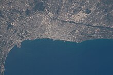
Taken from the ISS on June 23, 2022; downtown Chicago is at the center by the lake.

As of 2022, the metropolitan area had a population of 9,442,159. The population density was 1,312.3 per square mile. The racial makeup was 50.1% Non-Hispanic White, 23.4% were Hispanic, 15.5% were Non-Hispanic African Americans, 7.2% were Asian, 0.1% were Non-Hispanic Native American, 0.4% identified as “some other race,” and 3.2% were non-Hispanic multiracial.[27]

According to 2022 estimates from the American Community Survey, the largest ancestries in the Chicago metro area were Mexican (18%), African (17.7%), German (12.8%), Irish (9.9%), Polish (8%), Italian (5.9%), English (5.2%), Indian (2.7%), Puerto Rican (2.3%), Filipino (1.7%), Swedish (1.5%), and Chinese (1.4%).[28][29][30][31]

The suburbs, surrounded by easily annexed flat ground, have been expanding at a tremendous rate since the early 1960s. Aurora, Elgin, Joliet, and Naperville are noteworthy for being four of the few boomburbs outside the Sun Belt, West Coast and Mountain States regions, and exurban Kendall County ranked as the fastest-growing county (among counties with a population greater than 10,000) in the United States between the years 2000 and 2007.[32]

Settlement patterns in the Chicago metropolitan area tend to follow those in the city proper: the northern and northwestern suburbs are generally affluent and upper-middle class, while the southern suburbs (sometimes known as Chicago Southland) have somewhat lower median incomes and a cost of living, with the exception being the southwest suburbs which contain many upper-middle class areas. Another exception to this is the West Side, which has a somewhat lower median income, but the western suburbs contain many affluent and upper-middle class areas. According to the 2000 Census, DuPage County as a whole had the highest median household income of any county in the Midwestern United States, although there are individual cities and towns in other surrounding counties in the metro that have even higher median incomes.

According to 2022 estimates from the U.S. Census, poverty rates of the largest counties from least poverty to most are as follows: McHenry 4.0%, Dupage 6.7%, Will 6.9%, Kane 7.8%, Lake 8.0%, and Cook 13.6%.[33] However, Cook County, which contains luxury high rises and expensive houses in sections of the city and expensive houses along the waterfront in the North Shore area, would also have the highest percentage of expensive homes in the region.

In an in-depth historical analysis, Keating (2004, 2005) examined the origins of 233 settlements that by 1900 had become suburbs or city neighborhoods of the Chicago metropolitan area. The settlements began as farm centers (41%), industrial towns (30%), residential railroad suburbs (15%), and recreational/institutional centers (13%). Although relations between the different settlement types were at times contentious, there also was cooperation in such undertakings as the construction of high schools.[citation needed]

Population

[edit]

As the Chicago metropolitan area has grown, more counties have been partly or totally assimilated with the taking of each decennial census.

Census Area Area Type 2020 census 2010 census 2000 census 1990 census 1980 Census 1970 census 1960 census 1950 census
Chicago-Naperville-Joliet, IL-IN-WI Metropolitan 9,618,502 9,461,105 9,098,316 8,065,633 7,869,542 7,612,314 6,794,461 5,495,364
Cook County, Illinois Metropolitan 5,275,541 5,194,675 5,376,741 5,105,067 5,253,655 5,492,369 5,129,725 4,508,792
DeKalb County, Illinois Metropolitan 100,420 105,160 88,969 77,932 74,624 71,654 51,714 40,781
DuPage County, Illinois Metropolitan 932,877 916,924 904,161 781,666 658,835 491,882 313,459 154,599
Grundy County, Illinois Metropolitan 52,533 50,063 37,535 32,337 30,582 26,535 22,350 19,217
Kane County, Illinois Metropolitan 516,522 515,269 404,119 317,471 278,405 251,005 208,246 150,388
Kendall County, Illinois Metropolitan 131,869 114,736 54,544 39,413 37,202 26,374 17,540 12,115
McHenry County, Illinois Metropolitan 310,229 308,760 260,077 183,241 147,897 111,555 84,210 50,656
Will County, Illinois Metropolitan 696,355 677,560 502,266 357,313 324,460 249,498 191,617 134,336
Jasper County, Indiana Metropolitan 32,918 33,478 30,043 24,960 26,138 20,429 18,842 17,031
Lake County, Indiana Metropolitan 498,700 496,005 484,564 475,594 522,965 546,253 513,269 368,152
Newton County, Indiana Metropolitan 13,830 14,244 14,566 13,551 14,844 11,606 11,502 11,006
Porter County, Indiana Metropolitan 173,215 164,343 146,798 128,932 119,816 87,114 60,279 40,076
Lake County, Illinois Metropolitan 714,342 703,462 644,356 516,418 440,372 382,638 293,656 179,097
Kenosha County, Wisconsin Metropolitan 169,151 166,426 149,577 128,181 123,137 117,917 100,615 75,238
Kankakee County, Illinois Combined 107,502 113,449 103,833 96,255 102,926 97,250 92,063 73,524
LaSalle County, Illinois Combined 109,658 113,924 111,509 106,913 112,003 111,409 110,800 100,610
Bureau County, Illinois Combined 33,244 34,978 35,503 35,688 39,114 38,541 37,594 37,711
Putnam County, Illinois Combined 5,637 6,006 6,086 5,730 6,085 5,007 4,570 4,746
LaPorte County, Indiana Combined 112,417 111,467 110,106 107,066 108,632 105,342 95,111 76,808
Chicago-Naperville-Joliet, IL-IN-WI Combined 9,986,960 9,686,021 9,312,255 8,385,397 8,264,490 8,089,421 7,204,198 5,911,816

Counties highlighted in gray were not included in the MSA for that census. The CSA totals in blue are the totals of all the counties listed above, regardless of whether they were included in the Chicago Combined Statistical Area at the time.[34]

Principal municipalities

[edit]

Over 1,000,000 population

[edit]
  • Chicago (2,746,388)

Over 100,000 population

[edit]
  • Aurora, Illinois (180,542)
  • Joliet, Illinois (150,362)
  • Naperville, Illinois (149,540)
  • Elgin, Illinois (114,797)

Over 50,000 population

[edit]
  • Kenosha, Wisconsin (99,986)
  • Waukegan, Illinois (89,321)
  • Cicero, Illinois (85,268)
  • Schaumburg, Illinois (78,723)
  • Evanston, Illinois (78,110)
  • Hammond, Indiana (77,879)
  • Arlington Heights, Illinois (77,676)
  • Bolingbrook, Illinois (73,922)
  • Gary, Indiana (69,093)
  • Palatine, Illinois (67,908)
  • Skokie, Illinois (67,824)
  • Des Plaines, Illinois (60,675)
  • Orland Park, Illinois (58,703)
  • Oak Lawn, Illinois (58,362)
  • Berwyn, Illinois (57,250)
  • Mount Prospect, Illinois (56,852)
  • Tinley Park, Illinois (55,971)
  • Oak Park, Illinois (54,583)
  • Wheaton, Illinois (53,970)
  • Downers Grove, Illinois (50,247)
 
View of Chicago greater metropolitan region and the dense downtown area from the Willis Tower
 
View of Chicago greater metropolitan region and the North branch of the Chicago River from the Willis Tower

Urban areas within

[edit]

Within the boundary of the 16-county Chicago Combined Statistical Area lies the Chicago urban area, as well as 26 smaller urban areas.[35] Some of the urban areas below may partially cross into other statistical areas. Only those situated primarily within the Chicago combined statistical area are listed here.

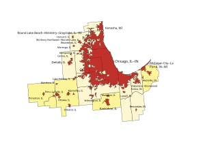
Urban areas contained within the Chicago combined statistical area as of the 2020 census:
  Urban areas
  Counties in the Chicago MSA
  Counties in the Chicago CSA but not the MSA
Urban area Population
(2020 census)
Land area
(sq mi)
Land area
(km2)
Density
(population / sq mi)
Density
(population / km2)
Chicago, IL–IN 8,671,746 2,337.89 6,055.09 3,709.2 1,432.1
Round Lake Beach–McHenry–Grayslake, IL–WI 261,835 127.61 330.52 2,051.8 792.2
Kenosha, WI 125,865 56.17 145.48 2,240.8 865.2
Michigan City–La Porte, IN–MI 71,367 49.16 127.32 1,451.7 560.5
Kankakee, IL 66,530 31.66 82.00 2,101.4 811.3
DeKalb, IL 64,736 25.63 66.39 2,525.6 975.1
Valparaiso–Shorewood Forest, IN 51,867 33.64 87.12 1,542.0 595.4
Peru–LaSalle, IL 29,763 21.45 55.56 1,387.4 535.7
Woodstock, IL 25,298 9.31 24.10 2,718.7 1,049.7
Ottawa, IL 20,122 9.99 25.87 2,014.2 777.7
Streator, IL 16,209 8.12 21.04 1,995.3 770.4
Coal City–Braidwood, IL 15,837 10.29 26.65 1,539.4 594.4
Morris, IL 15,740 8.64 22.37 1,822.2 703.5
Lowell, IN 10,747 5.28 13.66 2,037.2 786.6
Manteno, IL 10,437 6.01 15.56 1,736.8 670.6
Harvard, IL 9,376 4.36 11.30 2,148.7 829.6
Princeton, IL 7,979 6.20 16.06 1,287.1 497.0
Marengo, IL 7,509 3.81 9.86 1,971.5 761.2
Lake Holiday, IL 7,313 4.30 11.14 1,700.5 656.6
Mendota, IL 6,918 2.85 7.38 2,426.2 936.8
Wilmington, IL 6,388 3.95 10.23 1,617.3 624.5
McHenry Northwest–Wonder Lake, IL 5,758 2.35 6.08 2,453.6 947.4
Hampshire, IL 5,699 2.72 7.06 2,091.4 807.5
Rensselaer, IN 5,509 3.23 8.37 1,703.9 657.9
Genoa, IL 5,484 2.20 5.69 2,498.0 964.5
Westville, IN 5,189 2.10 5.45 2,466.0 952.1
Marseilles, IL 4,660 2.39 6.19 1,948.4 752.3

Economy

[edit]
Westward view from the Willis Tower in Chicago

The Chicago metropolitan area is home to the corporate headquarters of 57 Fortune 1000 companies, including AbbVie Inc., Allstate, Kraft Heinz, McDonald's, Mondelez International, Motorola, United Airlines, Walgreens, and more. The Chicago area also headquarters a wide variety of global financial institutions including Citadel LLC, Discover Financial Services, Morningstar, Inc., CNA Financial, and more. Chicago is home to the largest futures exchange in the world, the Chicago Mercantile Exchange. In March 2008, the Chicago Mercantile Exchange announced its acquisition of NYMEX Holdings Inc, the parent company of the New York Mercantile Exchange and Commodity Exchange. CME'S acquisition of NYMEX was completed in August 2008.

A key piece of infrastructure for several generations was the Union Stock Yards of Chicago, which from 1865 until 1971 penned and slaughtered millions of cattle and hogs into standardized cuts of beef and pork. This prompted poet Carl Sandburg to describe Chicago as the "Hog Butcher for the World".[36]

The Chicago area, meanwhile, began to produce significant quantities of telecommunications gear, electronics, steel, crude oil derivatives, automobiles, and industrial capital goods.

By the early 2000s, Illinois' economy had moved toward a dependence on high-value-added services, such as financial trading, higher education, logistics, and health care. In some cases, these services clustered around institutions that hearkened back to Illinois's earlier economies. For example, the Chicago Mercantile Exchange, a trading exchange for global derivatives, had begun its life as an agricultural futures market.

In 2007, the area ranked first among U.S. metro areas in the number of new and expanded corporate facilities.[37] It ranked third in 2008, behind the Houston–Sugar Land–Baytown and Dallas–Fort Worth metropolitan areas,[38] and ranked second behind the New York metropolitan area in 2009.[39]

The Wall Street Journal summarized the Chicago area's economy in November 2006 with the comment that "Chicago has survived by repeatedly reinventing itself."[40]

Transportation

[edit]
O'Hare Airport
Chicago 'L' in the Loop
Metra surface rail
The Eisenhower Expressway with the Chicago Transit Authority Blue Line tracks and the non-revenue ramp that leads to the Pink Line

Major airports

[edit]
  • Chicago O'Hare International Airport (ORD)
  • Chicago Midway International Airport (MDW)
  • Milwaukee Mitchell International Airport (MKE) (located in the adjacent Milwaukee metropolitan area)
  • Chicago Rockford International Airport (RFD) (located in the adjacent Rockford metropolitan area)
  • Gary/Chicago International Airport (GYY)

Commercial ports

[edit]
  • Port of Chicago
  • Port of Indiana-Burns Harbor

Transit systems

[edit]

Commercial freight

[edit]

Chicago has been at the center of the United States' railroad network since the 19th century. Almost all Class I railroads serve the area, the most in North America.[41]

Passenger

[edit]
  • Chicago Transit Authority trains, locally referred to as "the 'L'", (after "elevated train") serving Chicago and the near suburbs
  • Pace Suburban Bus operates suburban bus and regional vanpool, paratransit, and ride-matching services in the Chicagoland region.
  • Metra run by the Northeast Illinois Regional Commuter Railroad Corporation:
    • 4 lines serving southern Cook County and Will County
    • 3 lines serving western Cook County, DuPage County, and Kane County
    • 2 lines serving northern Cook County and Lake County
    • 1 line serving northern Cook County, Lake County, and Kenosha County
    • 1 line serving northwestern Cook County and McHenry County
  • South Shore Line shares the Metra Electric Line in Illinois and connects Chicago to Gary, Michigan City, and ending at South Bend.
  • Amtrak operates Union Station which is the major Amtrak passenger rail hub with connections to Metra and the within a few blocks of connections to several 'L' lines. Amtrak also operates a connecting station out of Joliet.

Major highways

[edit]

Interstates

[edit]
  • Interstate 41 (I-41) runs concurrently with Interstate 94 from the northern terminus of the Tri-State Tollway to Milwaukee.
  • Interstate 55 (I-55) is the Adlai Stevenson Expy.
  • I-355 is the Veterans Memorial Tollway (formerly North-South Tollway).
  • I-57 is unofficially the "West Leg" of the Dan Ryan Expy.
  • I-65 has no name, whether official or unofficial.
  • I-80 is officially called the Borman Expy (cosigned with I-94), Kingery Expy (cosigned with I-94 for 3 miles), Tri-State Tollway (cosigned with I-294 for 4 miles) and is unofficially called the Moline Expy west of I-294.
  • I-88 is the Ronald Reagan Memorial Tollway (formerly East-West Tollway)
  • I-90 is locally known as Jane Addams Tollway (formerly Northwest Tollway), John F. Kennedy Expy (cosigned with I-94), Dan Ryan Expy (cosigned with I-94), and Chicago Skyway Toll Bridge.
  • I-94 is Tri-State Tollway in Lake County, Edens Spur, Edens Expy, John F. Kennedy Expy (cosigned with I-90), Dan Ryan Expy (cosigned with I-90), Bishop Ford Frwy (formerly Calumet Expy), Kingery Expy (cosigned with I-80) and Borman Expy (cosigned with I-80).
  • I-190 is the John F. Kennedy Expy spur heading into Chicago-O'Hare Int'l Airport.
  • I-290 is the Dwight D. Eisenhower Expy.
  • I-294 is the Tri-State Tollway.

Other main highways

[edit]
  • US Routes in the Illinois part of the area include: US 6, US 12, US 14, US 20, US 30, US 34, US 41, US 45, and US 52.
  • Illinois Route 53, an arterial north–south state highway running through Grundy, Will, DuPage, Cook and Lake counties
  • Historic US Route 66's eastern terminus is in Chicago.

Major corridors

[edit]

In addition to the Chicago Loop, the metro area is home to a few important subregional corridors of commercial activities. Among them are:

  • Illinois Technology and Research Corridor, along the Ronald Reagan Memorial Tollway (Interstate 88)
  • Golden Corridor, along the Jane Addams Memorial Tollway (Interstate 90)
  • Lakeshore Corridor, along the Edens Expressway and Tri-State Tollway

Culture

[edit]

Sports

[edit]

Listing of the professional sports teams in the Chicago metropolitan area

Major league professional teams:

  • Major League Baseball (MLB)
    • Chicago Cubs
    • Chicago White Sox
  • National Football League (NFL)
    • Chicago Bears
  • National Basketball Association (NBA)
    • Chicago Bulls
  • National Hockey League (NHL)
    • Chicago Blackhawks
  • Major League Soccer (MLS)
    • Chicago Fire FC

Other professional teams:

  • Women's National Basketball Association (WNBA)
    • Chicago Sky
  • National Women's Soccer League (NWSL)
    • Chicago Stars FC
  • American Association of Professional Baseball (AA)
    • Chicago Dogs
    • Kane County Cougars
    • Gary SouthShore RailCats
  • American Hockey League (AHL)
    • Chicago Wolves
  • NBA G League (NBAGL)
    • Windy City Bulls
  • Major League Rugby (MLR)
    • Chicago Hounds

The Chicagoland Speedway oval track has hosted NASCAR Cup Series and IndyCar Series races. The Chicago Marathon is one of the World Marathon Majors. The Western Open and BMW Championship are PGA Tour tournaments that have been held primarily at golf courses near Chicago.

NCAA Division I College Sports Teams:

  • Atlantic 10 Conference
    • Loyola University Chicago Ramblers
  • Big East Conference
    • DePaul University Blue Demons
  • Big Ten Conference
    • Northwestern University Wildcats (Evanston)
  • Mid-American Conference
    • Northern Illinois University Huskies (DeKalb)
  • Missouri Valley Conference
    • University of Illinois Chicago Flames
    • Valparaiso University Beacons (Valparaiso, IN)
  • Northeast Conference
    • Chicago State University Cougars

Cuisine

[edit]
  • Chicago-style hot dog
  • Chicago-style pizza
  • Italian beef
  • Caramel popcorn

Media

[edit]

The two main newspapers are the Chicago Tribune and the Chicago Sun-Times. Local television channels broadcasting to the Chicago market include WBBM-TV 2 (CBS), WMAQ-TV 5 (NBC), WLS-TV 7 (ABC), WGN-TV 9 (Ind), WTTW 11 (PBS), MeTV 23, WCIU 26 (CW), WFLD 32 (FOX), WCPX-TV 38 (Ion), WSNS-TV 44 (Telemundo), WPWR-TV 50 (MyNetworkTV), and WJYS-TV 62 (The Way). Radio stations serving the area include: WBBM (AM), WBEZ, WGN (AM), WMBI, WLS (AM), and WSCR.

Education

[edit]
Whitney M. Young Magnet High School in Chicago

Elementary and secondary education within the Chicago metropolitan area is provided by dozens of different school districts, of which by far the largest is the Chicago Public Schools with 400,000 students.[42] Numerous private and religious school systems are also found in the region, as well as a growing number of charter schools. Racial inequalities in education in the region remain widespread, often breaking along district boundaries;[43] for instance, educational prospects vary widely for students in the Chicago Public Schools compared to those in some neighboring suburban schools.[44]

Historically, the Chicago metropolitan area has been at the center of a number of national educational movements, from the free-flowing Winnetka Plan to the regimented Taylorism of the Gary Plan.[45] In higher education, University of Chicago founder William Rainey Harper was a leading early advocate of the junior college movement; Joliet Junior College is the nation's oldest continuously operating junior college today.[46] Later U of C president Robert Maynard Hutchins was central to the Great Books movement, and programs of dialogic education arising from that legacy can be found today at the U of C, at Shimer College,[47] and in the City Colleges of Chicago and Oakton College in the Northwest suburbs.[48]

Area codes

[edit]

From 1947 until 1988, the Illinois portion of the Chicago metro area was served by a single area code, 312, which abutted the 815 area code. In 1988 the 708 area code was introduced and the 312 area code became exclusive to the city of Chicago.

It became common to call suburbanites "708'ers", in reference to their area code.

The 708 area code was partitioned in 1996 into three area codes, serving different portions of the metro area: 630, 708, and 847.

At the same time that the 708 area code was running out of phone numbers, the 312 area code in Chicago was also exhausting its supply of available numbers. As a result, the city of Chicago was divided into two area codes, 312 and 773. Rather than divide the city by a north–south area code, the central business district retained the 312 area code, while the remainder of the city took the new 773 code.

In 2002, the 847 area code was supplemented with the overlay area code 224. In February 2007, the 815 area code (serving outlying portions of the metro area) was supplemented with the overlay area code 779. In October 2007, the overlay area code 331 was implemented to supplement the 630 area with additional numbers.

Plans are in place for overlay codes in the 708, 773, and 312 regions as those area codes become exhausted in the future.

  • 312 Chicago - City (The Loop and central neighborhoods, e.g. the Near North Side)
  • 773 Chicago - City (Everywhere else within the city limits, excluding central area)
  • 872 Chicago - City (overlay for 312 & 773, effective November 7, 2009)
  • 847/224 (North and Northwest Suburbs)
  • 630/331 (Outer Western Suburbs)
  • 708 (South and Near West Suburbs)
  • 815/779 (Rockford & Joliet: Far Northwest/Southwest Suburbs)
  • 219 (Northwest Indiana)
  • 574 (North-central Indiana)
  • 262 (Southeast Wisconsin surrounding Milwaukee County)

Proposed overlays

[edit]
  • 464 overlay for 708 (January 21, 2022, rollout)

See also

[edit]
  • Index of Illinois-related articles

References

[edit]
  1. ^ a b "Elevations of the 50 Largest Cities". U.S. Geological Survey. Archived from the original on November 9, 2013. Retrieved January 23, 2016. Chicago city proper only
  2. ^ "2020 Population and Housing State Data". United States Census Bureau, Population Division. August 12, 2021. Retrieved November 19, 2021.
  3. ^ "USA: Combined Metropolitan Areas". CityPopulation.de. August 2021. Retrieved November 19, 2021.
  4. ^ "Total Gross Domestic Product for Chicago-Naperville-Elgin, IL-IN-WI (MSA)". Federal Reserve Economic Data. Federal Reserve Bank of St. Louis.
  5. ^ "Annual Estimates of the Resident Population for Combined Statistical Areas in the United States and Puerto Rico: April 1, 2010 to July 1, 2019 (CSA-EST2019-ANNRES)". United States Census Bureau, Population Division. March 2020. Retrieved May 5, 2020.
  6. ^ "Annual Estimates of the Resident Population for Metropolitan Statistical Areas in the United States and Puerto Rico: April 1, 2010 to July 1, 2019 (CBSA-MET-EST2019-ANNRES)". United States Census Bureau, Population Division. March 2020. Retrieved May 5, 2020.
  7. ^ "CAEMP25N Total Full-Time and Part-Time Employment by NAICS Industry 1/ 2018". Bureau of Economic Analysis. November 14, 2019. Retrieved May 5, 2020.
  8. ^ "CAGDP1 Gross Domestic Product (GDP) summary by county and metropolitan area 2018". Bureau of Economic Analysis. December 12, 2019. Retrieved May 5, 2020.
  9. ^ "Economy". Worldbusinesschicago.com. Retrieved October 3, 2017.
  10. ^ "Chicago Named Nation's Top Metro Area for Corporate Relocation For the Sixth Straight Year". World Business Chicago. March 25, 2019. Retrieved July 21, 2019.
  11. ^ a b c "Metropolitan and Micropolitan Statistical Areas Population Totals and Components of Change: 2020-2021". Census.gov. United States Census Bureau. Retrieved February 12, 2023.
  12. ^ "The World's Cities in 2018" (PDF). United Nations, Department of Economic and Social Affairs, Population Division. Retrieved May 5, 2020.
  13. ^ As defined by Construction Data Company.
  14. ^ a b Fuller, Jack (2005). "Chicagoland". The Electronic Encyclopedia of Chicago. Chicago Historical Society. Retrieved February 20, 2010.
  15. ^ "The Press: The Colonel's Century". TIME. June 9, 1947. Archived from the original on September 18, 2008. Retrieved February 20, 2010.
  16. ^ O'Donnell Bennett, James (July 27, 1926). "Chicagoland's Shrines: A Tour of Discoveries". Chicago Daily Tribune (1923-1963). Archived from the original on September 10, 2010. Retrieved February 20, 2010.
  17. ^ Cronon (1992); Keating (2005); Keating (2004)
  18. ^ "Classifieds map of Chicagoland". Chicagotribune.com. Retrieved May 30, 2011.
  19. ^ [1] Archived November 10, 2006, at the Wayback Machine
  20. ^ "About Chicagoland". Chicagoland Chamber of Commerce. Archived from the original on October 29, 2013. Retrieved October 25, 2013.
  21. ^ "Bidtool Coverage area: Chicago, Indiana, Wisconsin, Colorado, Kentucky project leads". Bidtool.net. Archived from the original on July 15, 2011. Retrieved May 30, 2011.
  22. ^ Mariner, Richard D. (July 10, 2018). "Collar Counties". The Electrictronic Encyclopedia of Chicago. Chicago, IL: Chicago Historical Society (2005), Newberry Library (2004).
  23. ^ "Chicago Metropolitan Agency for Planning". Chicagoareaplanning.org. Archived from the original on August 12, 2006. Retrieved May 30, 2011.
  24. ^ "About - CMAP". Cmap.illinois.gov. Retrieved September 7, 2015.
  25. ^ Nowak, David J.; Hoehn, Robert E. III; Bodine, Allison R.; Crane, Daniel E.; Dwyer, John F.; Bonnewell, Veta; Watson, Gary. (September 17, 2013). "Urban trees and forests of the Chicago region". Nrs.fs.fed.us. doi:10.2737/NRS-RB-84. Retrieved September 7, 2015.
  26. ^ "Regional Tree Census | The Morton Arboretum". Mortonarb.org. Archived from the original on May 15, 2015. Retrieved September 7, 2015.
  27. ^ "Grid View: Table B03002 - Census Reporter". censusreporter.org. Retrieved June 29, 2024.
  28. ^ "Grid View: Table B04006 - Census Reporter". censusreporter.org. Retrieved June 29, 2024.
  29. ^ "Grid View: Table B02018 - Census Reporter". censusreporter.org. Retrieved June 29, 2024.
  30. ^ "Grid View: Table B03001 - Census Reporter". censusreporter.org. Retrieved June 29, 2024.
  31. ^ "Grid View: Table B02009 - Census Reporter". censusreporter.org. Retrieved June 29, 2024.
  32. ^ "Kendall County is fastest growing in the nation". Daily Herald. Retrieved May 30, 2011.
  33. ^ "Census profile: Chicago-Naperville-Elgin, IL-IN-WI Metro Area". Census Reporter. Retrieved June 29, 2024.
  34. ^ "Historical Metropolitan Area Definitions". Census.gov. Retrieved May 30, 2011.
  35. ^ "List of 2020 Census Urban Areas". United States Census Bureau. Retrieved January 7, 2023.
  36. ^ Carl Sandburg. "Chicago". Poetry: A Magazine of Verse, vol. 3, no. 6 (March 1914):191-192.
  37. ^ RON STARNER. "TOP METROS OF 2007 - Site Selection magazine, March 2008". Siteselection.com. Retrieved May 30, 2011.
  38. ^ RON STARNER (March 9, 2009). "TOP METROS OF 2008 - Site Selection magazine, March 2009". Siteselection.com. Retrieved May 30, 2011.
  39. ^ "TOP METROS OF 2009 - Site Selection Magazine, March 2010". Siteselection.com. Archived from the original on July 2, 2011. Retrieved May 30, 2011.
  40. ^ Brat, Ilan (November 8, 2006). "Tale of a Warehouse Shows How Chicago Weathers a Decline". The Wall Street Journal. p. A1. Retrieved February 20, 2010.
  41. ^ "Chicago Highlighted as the US Railroad Capital by Trains Magazine". WTTW. February 23, 2017. Retrieved March 23, 2019.
  42. ^ "About CPS". Chicago Public Schools. Retrieved January 26, 2015.
  43. ^ Moore, Natalie (November 12, 2014). "Why so few white kids land in CPS — and why it matters". WBEZ. Archived from the original on January 17, 2015. Retrieved January 26, 2015.
  44. ^ Bogira, Steve (October 17, 2012). "Two students, two high schools, two divergent paths to college". Chicago Reader.
  45. ^ Thiede, Robert. "Gary Plan". Britannica.com. Retrieved January 16, 2015.
  46. ^ Sydow, Debbie; Alfred, Richard (2012). Re-visioning Community Colleges: Positioning for Innovation. Rowman & Littlefield Publishers. p. 13. ISBN 978-1442214880.
  47. ^ Ronson, Jon (December 6, 2014). "Shimer College: The Worst School in America?". The Guardian.
  48. ^ "Great Books program". Oakton Community College. Retrieved January 26, 2015.

Further reading

[edit]
  • Fischer, Paul B. (July 28, 1993). Racial and Locational Patterns of Subsidized Housing in the Chicago Suburbs: A Report to the MacArthur Foundation (Archive). Lake Forest, Ill.: Lake Forest College. Report to the MacArthur Foundation.
  • Lewinnek, Elaine (2014). The Working Man's Reward: Chicago's Early Suburbs and the Roots of American Sprawl. Oxford: Oxford University Press.
[edit]
  • Encyclopedia of Chicago (2004), comprehensive coverage of city and suburbs, past and present
  • U.S. Census Urbanized Area Outline Map (2000)
  • Chicago-Naperville-Michigan City, IL-IN-WI Combined Statistical Area (2012) map
  • Illinois CBSAs and Counties (2013) map
  • U.S. Census Bureau Chicago city, Illinois QuickFacts
  • Metropolitan and Micropolitan Statistical Areas
  • About Metropolitan and Micropolitan Statistical Areas
  • History of Metropolitan Areas
  • Metropolitan and Micropolitan Statistical Areas Population Totals and Components of Change: 2010–2019


The Leaning Tower of Pisa – an example of a problem due to deformation of soil
Slope instability issues for a temporary flood control levee in North Dakota, 2009
Earthwork in Germany
Fox Glacier, New Zealand: Soil produced and transported by intense weathering and erosion

Soil mechanics is a branch of soil physics and applied mechanics that describes the behavior of soils. It differs from fluid mechanics and solid mechanics in the sense that soils consist of a heterogeneous mixture of fluids (usually air and water) and particles (usually clay, silt, sand, and gravel) but soil may also contain organic solids and other matter.[1][2][3][4] Along with rock mechanics, soil mechanics provides the theoretical basis for analysis in geotechnical engineering,[5] a subdiscipline of civil engineering, and engineering geology, a subdiscipline of geology. Soil mechanics is used to analyze the deformations of and flow of fluids within natural and man-made structures that are supported on or made of soil, or structures that are buried in soils.[6] Example applications are building and bridge foundations, retaining walls, dams, and buried pipeline systems. Principles of soil mechanics are also used in related disciplines such as geophysical engineering, coastal engineering, agricultural engineering, and hydrology.

This article describes the genesis and composition of soil, the distinction between pore water pressure and inter-granular effective stress, capillary action of fluids in the soil pore spaces, soil classification, seepage and permeability, time dependent change of volume due to squeezing water out of tiny pore spaces, also known as consolidation, shear strength and stiffness of soils. The shear strength of soils is primarily derived from friction between the particles and interlocking, which are very sensitive to the effective stress.[7][6] The article concludes with some examples of applications of the principles of soil mechanics such as slope stability, lateral earth pressure on retaining walls, and bearing capacity of foundations.

Genesis and composition of soils

[edit]

Genesis

[edit]

The primary mechanism of soil creation is the weathering of rock. All rock types (igneous rock, metamorphic rock and sedimentary rock) may be broken down into small particles to create soil. Weathering mechanisms are physical weathering, chemical weathering, and biological weathering [1][2][3] Human activities such as excavation, blasting, and waste disposal, may also create soil. Over geologic time, deeply buried soils may be altered by pressure and temperature to become metamorphic or sedimentary rock, and if melted and solidified again, they would complete the geologic cycle by becoming igneous rock.[3]

Physical weathering includes temperature effects, freeze and thaw of water in cracks, rain, wind, impact and other mechanisms. Chemical weathering includes dissolution of matter composing a rock and precipitation in the form of another mineral. Clay minerals, for example can be formed by weathering of feldspar, which is the most common mineral present in igneous rock.

The most common mineral constituent of silt and sand is quartz, also called silica, which has the chemical name silicon dioxide. The reason that feldspar is most common in rocks but silica is more prevalent in soils is that feldspar is much more soluble than silica.

Silt, Sand, and Gravel are basically little pieces of broken rocks.

According to the Unified Soil Classification System, silt particle sizes are in the range of 0.002 mm to 0.075 mm and sand particles have sizes in the range of 0.075 mm to 4.75 mm.

Gravel particles are broken pieces of rock in the size range 4.75 mm to 100 mm. Particles larger than gravel are called cobbles and boulders.[1][2]

Transport

[edit]
Example soil horizons. a) top soil and colluvium b) mature residual soil c) young residual soil d) weathered rock

Soil deposits are affected by the mechanism of transport and deposition to their location. Soils that are not transported are called residual soils—they exist at the same location as the rock from which they were generated. Decomposed granite is a common example of a residual soil. The common mechanisms of transport are the actions of gravity, ice, water, and wind. Wind blown soils include dune sands and loess. Water carries particles of different size depending on the speed of the water, thus soils transported by water are graded according to their size. Silt and clay may settle out in a lake, and gravel and sand collect at the bottom of a river bed. Wind blown soil deposits (aeolian soils) also tend to be sorted according to their grain size. Erosion at the base of glaciers is powerful enough to pick up large rocks and boulders as well as soil; soils dropped by melting ice can be a well graded mixture of widely varying particle sizes. Gravity on its own may also carry particles down from the top of a mountain to make a pile of soil and boulders at the base; soil deposits transported by gravity are called colluvium.[1][2]

The mechanism of transport also has a major effect on the particle shape. For example, low velocity grinding in a river bed will produce rounded particles. Freshly fractured colluvium particles often have a very angular shape.

Soil composition

[edit]

Soil mineralogy

[edit]

Silts, sands and gravels are classified by their size, and hence they may consist of a variety of minerals. Owing to the stability of quartz compared to other rock minerals, quartz is the most common constituent of sand and silt. Mica, and feldspar are other common minerals present in sands and silts.[1] The mineral constituents of gravel may be more similar to that of the parent rock.

The common clay minerals are montmorillonite or smectite, illite, and kaolinite or kaolin. These minerals tend to form in sheet or plate like structures, with length typically ranging between 10−7 m and 4x10⁻⁶ m and thickness typically ranging between 10−9 m and 2x10⁻⁶ m, and they have a relatively large specific surface area. The specific surface area (SSA) is defined as the ratio of the surface area of particles to the mass of the particles. Clay minerals typically have specific surface areas in the range of 10 to 1,000 square meters per gram of solid.[3] Due to the large surface area available for chemical, electrostatic, and van der Waals interaction, the mechanical behavior of clay minerals is very sensitive to the amount of pore fluid available and the type and amount of dissolved ions in the pore fluid.[1]

The minerals of soils are predominantly formed by atoms of oxygen, silicon, hydrogen, and aluminum, organized in various crystalline forms. These elements along with calcium, sodium, potassium, magnesium, and carbon constitute over 99 per cent of the solid mass of soils.[1]

Grain size distribution

[edit]

Soils consist of a mixture of particles of different size, shape and mineralogy. Because the size of the particles obviously has a significant effect on the soil behavior, the grain size and grain size distribution are used to classify soils. The grain size distribution describes the relative proportions of particles of various sizes. The grain size is often visualized in a cumulative distribution graph which, for example, plots the percentage of particles finer than a given size as a function of size. The median grain size, , is the size for which 50% of the particle mass consists of finer particles. Soil behavior, especially the hydraulic conductivity, tends to be dominated by the smaller particles, hence, the term "effective size", denoted by , is defined as the size for which 10% of the particle mass consists of finer particles.

Sands and gravels that possess a wide range of particle sizes with a smooth distribution of particle sizes are called well graded soils. If the soil particles in a sample are predominantly in a relatively narrow range of sizes, the sample is uniformly graded. If a soil sample has distinct gaps in the gradation curve, e.g., a mixture of gravel and fine sand, with no coarse sand, the sample may be gap graded. Uniformly graded and gap graded soils are both considered to be poorly graded. There are many methods for measuring particle-size distribution. The two traditional methods are sieve analysis and hydrometer analysis.

Sieve analysis
[edit]
Sieve

The size distribution of gravel and sand particles are typically measured using sieve analysis. The formal procedure is described in ASTM D6913-04(2009).[8] A stack of sieves with accurately dimensioned holes between a mesh of wires is used to separate the particles into size bins. A known volume of dried soil, with clods broken down to individual particles, is put into the top of a stack of sieves arranged from coarse to fine. The stack of sieves is shaken for a standard period of time so that the particles are sorted into size bins. This method works reasonably well for particles in the sand and gravel size range. Fine particles tend to stick to each other, and hence the sieving process is not an effective method. If there are a lot of fines (silt and clay) present in the soil it may be necessary to run water through the sieves to wash the coarse particles and clods through.

A variety of sieve sizes are available. The boundary between sand and silt is arbitrary. According to the Unified Soil Classification System, a #4 sieve (4 openings per inch) having 4.75 mm opening size separates sand from gravel and a #200 sieve with an 0.075 mm opening separates sand from silt and clay. According to the British standard, 0.063 mm is the boundary between sand and silt, and 2 mm is the boundary between sand and gravel.[3]

Hydrometer analysis
[edit]

The classification of fine-grained soils, i.e., soils that are finer than sand, is determined primarily by their Atterberg limits, not by their grain size. If it is important to determine the grain size distribution of fine-grained soils, the hydrometer test may be performed. In the hydrometer tests, the soil particles are mixed with water and shaken to produce a dilute suspension in a glass cylinder, and then the cylinder is left to sit. A hydrometer is used to measure the density of the suspension as a function of time. Clay particles may take several hours to settle past the depth of measurement of the hydrometer. Sand particles may take less than a second. Stokes' law provides the theoretical basis to calculate the relationship between sedimentation velocity and particle size. ASTM provides the detailed procedures for performing the Hydrometer test.

Clay particles can be sufficiently small that they never settle because they are kept in suspension by Brownian motion, in which case they may be classified as colloids.

Mass-volume relations

[edit]
A phase diagram of soil indicating the masses and volumes of air, solid, water, and voids

There are a variety of parameters used to describe the relative proportions of air, water and solid in a soil. This section defines these parameters and some of their interrelationships.[2][6] The basic notation is as follows:

, , and represent the volumes of air, water and solids in a soil mixture;
, , and represent the weights of air, water and solids in a soil mixture;
, , and represent the masses of air, water and solids in a soil mixture;
, , and represent the densities of the constituents (air, water and solids) in a soil mixture;

Note that the weights, W, can be obtained by multiplying the mass, M, by the acceleration due to gravity, g; e.g.,

Specific Gravity is the ratio of the density of one material compared to the density of pure water ().

Specific gravity of solids,

Note that specific weight, conventionally denoted by the symbol may be obtained by multiplying the density ( ) of a material by the acceleration due to gravity, .

Density, bulk density, or wet density, , are different names for the density of the mixture, i.e., the total mass of air, water, solids divided by the total volume of air water and solids (the mass of air is assumed to be zero for practical purposes):

Dry density, , is the mass of solids divided by the total volume of air water and solids:

Buoyant density, , defined as the density of the mixture minus the density of water is useful if the soil is submerged under water:

where is the density of water

Water content, is the ratio of mass of water to mass of solid. It is easily measured by weighing a sample of the soil, drying it out in an oven and re-weighing. Standard procedures are described by ASTM.

Void ratio, , is the ratio of the volume of voids to the volume of solids:

Porosity, , is the ratio of volume of voids to the total volume, and is related to the void ratio:

Degree of saturation, , is the ratio of the volume of water to the volume of voids:

From the above definitions, some useful relationships can be derived by use of basic algebra.

Soil classification

[edit]

Geotechnical engineers classify the soil particle types by performing tests on disturbed (dried, passed through sieves, and remolded) samples of the soil. This provides information about the characteristics of the soil grains themselves. Classification of the types of grains present in a soil does not[clarification needed] account for important effects of the structure or fabric of the soil, terms that describe compactness of the particles and patterns in the arrangement of particles in a load carrying framework as well as the pore size and pore fluid distributions. Engineering geologists also classify soils based on their genesis and depositional history.

Classification of soil grains

[edit]

In the US and other countries, the Unified Soil Classification System (USCS) is often used for soil classification. Other classification systems include the British Standard BS 5930 and the AASHTO soil classification system.[3]

Classification of sands and gravels

[edit]

In the USCS, gravels (given the symbol G) and sands (given the symbol S) are classified according to their grain size distribution. For the USCS, gravels may be given the classification symbol GW (well-graded gravel), GP (poorly graded gravel), GM (gravel with a large amount of silt), or GC (gravel with a large amount of clay). Likewise sands may be classified as being SW, SP, SM or SC. Sands and gravels with a small but non-negligible amount of fines (5–12%) may be given a dual classification such as SW-SC.

Atterberg limits

[edit]

Clays and Silts, often called 'fine-grained soils', are classified according to their Atterberg limits; the most commonly used Atterberg limits are the liquid limit (denoted by LL or ), plastic limit (denoted by PL or ), and shrinkage limit (denoted by SL).

The liquid limit is the water content at which the soil behavior transitions from a plastic solid to a liquid. The plastic limit is the water content at which the soil behavior transitions from that of a plastic solid to a brittle solid. The Shrinkage Limit corresponds to a water content below which the soil will not shrink as it dries. The consistency of fine grained soil varies in proportional to the water content in a soil.

As the transitions from one state to another are gradual, the tests have adopted arbitrary definitions to determine the boundaries of the states. The liquid limit is determined by measuring the water content for which a groove closes after 25 blows in a standard test.[9][clarification needed] Alternatively, a fall cone test apparatus may be used to measure the liquid limit. The undrained shear strength of remolded soil at the liquid limit is approximately 2 kPa.[4][10] The plastic limit is the water content below which it is not possible to roll by hand the soil into 3 mm diameter cylinders. The soil cracks or breaks up as it is rolled down to this diameter. Remolded soil at the plastic limit is quite stiff, having an undrained shear strength of the order of about 200 kPa.[4][10]

The plasticity index of a particular soil specimen is defined as the difference between the liquid limit and the plastic limit of the specimen; it is an indicator of how much water the soil particles in the specimen can absorb, and correlates with many engineering properties like permeability, compressibility, shear strength and others. Generally, the clay having high plasticity have lower permeability and also they are also difficult to be compacted.

Classification of silts and clays

[edit]

According to the Unified Soil Classification System (USCS), silts and clays are classified by plotting the values of their plasticity index and liquid limit on a plasticity chart. The A-Line on the chart separates clays (given the USCS symbol C) from silts (given the symbol M). LL=50% separates high plasticity soils (given the modifier symbol H) from low plasticity soils (given the modifier symbol L). A soil that plots above the A-line and has LL>50% would, for example, be classified as CH. Other possible classifications of silts and clays are ML, CL and MH. If the Atterberg limits plot in the"hatched" region on the graph near the origin, the soils are given the dual classification 'CL-ML'.

[edit]

Liquidity index

[edit]

The effects of the water content on the strength of saturated remolded soils can be quantified by the use of the liquidity index, LI:

When the LI is 1, remolded soil is at the liquid limit and it has an undrained shear strength of about 2 kPa. When the soil is at the plastic limit, the LI is 0 and the undrained shear strength is about 200 kPa.[4][11]

Relative density

[edit]

The density of sands (cohesionless soils) is often characterized by the relative density,

where: is the "maximum void ratio" corresponding to a very loose state, is the "minimum void ratio" corresponding to a very dense state and is the in situ void ratio. Methods used to calculate relative density are defined in ASTM D4254-00(2006).[12]

Thus if the sand or gravel is very dense, and if the soil is extremely loose and unstable.

Seepage: steady state flow of water

[edit]
A cross section showing the water table varying with surface topography as well as a perched water table
In soil mechanics, seepage is the movement of water through soil. If fluid pressures in a soil deposit are uniformly increasing with depth according to , where is the depth below the water table, then hydrostatic conditions will prevail and the fluids will not be flowing through the soil. However, if the water table is sloping or there is a perched water table as indicated in the accompanying sketch, then seepage will occur. For steady state seepage, the seepage velocities are not varying with time. If the water tables are changing levels with time, or if the soil is in the process of consolidation, then steady state conditions do not apply.

Effective stress and capillarity: hydrostatic conditions

[edit]
Spheres immersed in water, reducing effective stress

To understand the mechanics of soils it is necessary to understand how normal stresses and shear stresses are shared by the different phases. Neither gas nor liquid provide significant resistance to shear stress. The shear resistance of soil is provided by friction and interlocking of the particles. The friction depends on the intergranular contact stresses between solid particles. The normal stresses, on the other hand, are shared by the fluid and the particles.[7] Although the pore air is relatively compressible, and hence takes little normal stress in most geotechnical problems, liquid water is relatively incompressible and if the voids are saturated with water, the pore water must be squeezed out in order to pack the particles closer together.

The principle of effective stress, introduced by Karl Terzaghi, states that the effective stress σ' (i.e., the average intergranular stress between solid particles) may be calculated by a simple subtraction of the pore pressure from the total stress:

[7]

where σ is the total stress and u is the pore pressure. It is not practical to measure σ' directly, so in practice the vertical effective stress is calculated from the pore pressure and vertical total stress. The distinction between the terms pressure and stress is also important. By definition, pressure at a point is equal in all directions but stresses at a point can be different in different directions. In soil mechanics, compressive stresses and pressures are considered to be positive and tensile stresses are considered to be negative, which is different from the solid mechanics sign convention for stress.

Total stress

[edit]

For level ground conditions, the total vertical stress at a point, , on average, is the weight of everything above that point per unit area. The vertical stress beneath a uniform surface layer with density , and thickness is for example:

where is the acceleration due to gravity, and is the unit weight of the overlying layer. If there are multiple layers of soil or water above the point of interest, the vertical stress may be calculated by summing the product of the unit weight and thickness of all of the overlying layers. Total stress increases with increasing depth in proportion to the density of the overlying soil.

It is not possible to calculate the horizontal total stress in this way. Lateral earth pressures are addressed elsewhere.

Pore water pressure

[edit]

Hydrostatic conditions

[edit]
Water is drawn into a small tube by surface tension. Water pressure, u, is negative above and positive below the free water surface.

If the soil pores are filled with water that is not flowing but is static, the pore water pressures will be hydrostatic. The water table is located at the depth where the water pressure is equal to the atmospheric pressure. For hydrostatic conditions, the water pressure increases linearly with depth below the water table:

where is the density of water, and is the depth below the water table.

Capillary action

[edit]

Due to surface tension, water will rise up in a small capillary tube above a free surface of water. Likewise, water will rise up above the water table into the small pore spaces around the soil particles. In fact the soil may be completely saturated for some distance above the water table. Above the height of capillary saturation, the soil may be wet but the water content will decrease with elevation. If the water in the capillary zone is not moving, the water pressure obeys the equation of hydrostatic equilibrium, , but note that , is negative above the water table. Hence, hydrostatic water pressures are negative above the water table. The thickness of the zone of capillary saturation depends on the pore size, but typically, the heights vary between a centimeter or so for coarse sand to tens of meters for a silt or clay.[3] In fact the pore space of soil is a uniform fractal e.g. a set of uniformly distributed D-dimensional fractals of average linear size L. For the clay soil it has been found that L=0.15 mm and D=2.7.[13]

The surface tension of water explains why the water does not drain out of a wet sand castle or a moist ball of clay. Negative water pressures make the water stick to the particles and pull the particles to each other, friction at the particle contacts make a sand castle stable. But as soon as a wet sand castle is submerged below a free water surface, the negative pressures are lost and the castle collapses. Considering the effective stress equation, if the water pressure is negative, the effective stress may be positive, even on a free surface (a surface where the total normal stress is zero). The negative pore pressure pulls the particles together and causes compressive particle to particle contact forces. Negative pore pressures in clayey soil can be much more powerful than those in sand. Negative pore pressures explain why clay soils shrink when they dry and swell as they are wetted. The swelling and shrinkage can cause major distress, especially to light structures and roads.[14]

Later sections of this article address the pore water pressures for seepage and consolidation problems.

Consolidation: transient flow of water

[edit]
Consolidation analogy. The piston is supported by water underneath and a spring. When a load is applied to the piston, water pressure increases to support the load. As the water slowly leaks through the small hole, the load is transferred from the water pressure to the spring force.

Consolidation is a process by which soils decrease in volume. It occurs when stress is applied to a soil that causes the soil particles to pack together more tightly, therefore reducing volume. When this occurs in a soil that is saturated with water, water will be squeezed out of the soil. The time required to squeeze the water out of a thick deposit of clayey soil layer might be years. For a layer of sand, the water may be squeezed out in a matter of seconds. A building foundation or construction of a new embankment will cause the soil below to consolidate and this will cause settlement which in turn may cause distress to the building or embankment. Karl Terzaghi developed the theory of one-dimensional consolidation which enables prediction of the amount of settlement and the time required for the settlement to occur.[15] Afterwards, Maurice Biot fully developed the three-dimensional soil consolidation theory, extending the one-dimensional model previously developed by Terzaghi to more general hypotheses and introducing the set of basic equations of Poroelasticity.[7] Soils are tested with an oedometer test to determine their compression index and coefficient of consolidation.

When stress is removed from a consolidated soil, the soil will rebound, drawing water back into the pores and regaining some of the volume it had lost in the consolidation process. If the stress is reapplied, the soil will re-consolidate again along a recompression curve, defined by the recompression index. Soil that has been consolidated to a large pressure and has been subsequently unloaded is considered to be overconsolidated. The maximum past vertical effective stress is termed the preconsolidation stress. A soil which is currently experiencing the maximum past vertical effective stress is said to be normally consolidated. The overconsolidation ratio, (OCR) is the ratio of the maximum past vertical effective stress to the current vertical effective stress. The OCR is significant for two reasons: firstly, because the compressibility of normally consolidated soil is significantly larger than that for overconsolidated soil, and secondly, the shear behavior and dilatancy of clayey soil are related to the OCR through critical state soil mechanics; highly overconsolidated clayey soils are dilatant, while normally consolidated soils tend to be contractive.[2][3][4]

Shear behavior: stiffness and strength

[edit]
Typical stress strain curve for a drained dilatant soil

The shear strength and stiffness of soil determines whether or not soil will be stable or how much it will deform. Knowledge of the strength is necessary to determine if a slope will be stable, if a building or bridge might settle too far into the ground, and the limiting pressures on a retaining wall. It is important to distinguish between failure of a soil element and the failure of a geotechnical structure (e.g., a building foundation, slope or retaining wall); some soil elements may reach their peak strength prior to failure of the structure. Different criteria can be used to define the "shear strength" and the "yield point" for a soil element from a stress–strain curve. One may define the peak shear strength as the peak of a stress–strain curve, or the shear strength at critical state as the value after large strains when the shear resistance levels off. If the stress–strain curve does not stabilize before the end of shear strength test, the "strength" is sometimes considered to be the shear resistance at 15–20% strain.[14] The shear strength of soil depends on many factors including the effective stress and the void ratio.

The shear stiffness is important, for example, for evaluation of the magnitude of deformations of foundations and slopes prior to failure and because it is related to the shear wave velocity. The slope of the initial, nearly linear, portion of a plot of shear stress as a function of shear strain is called the shear modulus

Friction, interlocking and dilation

[edit]
Angle of repose

Soil is an assemblage of particles that have little to no cementation while rock (such as sandstone) may consist of an assembly of particles that are strongly cemented together by chemical bonds. The shear strength of soil is primarily due to interparticle friction and therefore, the shear resistance on a plane is approximately proportional to the effective normal stress on that plane.[3] The angle of internal friction is thus closely related to the maximum stable slope angle, often called the angle of repose.

But in addition to friction, soil derives significant shear resistance from interlocking of grains. If the grains are densely packed, the grains tend to spread apart from each other as they are subject to shear strain. The expansion of the particle matrix due to shearing was called dilatancy by Osborne Reynolds.[11] If one considers the energy required to shear an assembly of particles there is energy input by the shear force, T, moving a distance, x and there is also energy input by the normal force, N, as the sample expands a distance, y.[11] Due to the extra energy required for the particles to dilate against the confining pressures, dilatant soils have a greater peak strength than contractive soils. Furthermore, as dilative soil grains dilate, they become looser (their void ratio increases), and their rate of dilation decreases until they reach a critical void ratio. Contractive soils become denser as they shear, and their rate of contraction decreases until they reach a critical void ratio.

A critical state line separates the dilatant and contractive states for soil.

The tendency for a soil to dilate or contract depends primarily on the confining pressure and the void ratio of the soil. The rate of dilation is high if the confining pressure is small and the void ratio is small. The rate of contraction is high if the confining pressure is large and the void ratio is large. As a first approximation, the regions of contraction and dilation are separated by the critical state line.

Failure criteria

[edit]

After a soil reaches the critical state, it is no longer contracting or dilating and the shear stress on the failure plane is determined by the effective normal stress on the failure plane and critical state friction angle :

The peak strength of the soil may be greater, however, due to the interlocking (dilatancy) contribution. This may be stated:

where . However, use of a friction angle greater than the critical state value for design requires care. The peak strength will not be mobilized everywhere at the same time in a practical problem such as a foundation, slope or retaining wall. The critical state friction angle is not nearly as variable as the peak friction angle and hence it can be relied upon with confidence.[3][4][11]

Not recognizing the significance of dilatancy, Coulomb proposed that the shear strength of soil may be expressed as a combination of adhesion and friction components:[11]

It is now known that the and parameters in the last equation are not fundamental soil properties.[3][6][11][16] In particular, and are different depending on the magnitude of effective stress.[6][16] According to Schofield (2006),[11] the longstanding use of in practice has led many engineers to wrongly believe that is a fundamental parameter. This assumption that and are constant can lead to overestimation of peak strengths.[3][16]

Structure, fabric, and chemistry

[edit]

In addition to the friction and interlocking (dilatancy) components of strength, the structure and fabric also play a significant role in the soil behavior. The structure and fabric include factors such as the spacing and arrangement of the solid particles or the amount and spatial distribution of pore water; in some cases cementitious material accumulates at particle-particle contacts. Mechanical behavior of soil is affected by the density of the particles and their structure or arrangement of the particles as well as the amount and spatial distribution of fluids present (e.g., water and air voids). Other factors include the electrical charge of the particles, chemistry of pore water, chemical bonds (i.e. cementation -particles connected through a solid substance such as recrystallized calcium carbonate) [1][16]

Drained and undrained shear

[edit]
Moist sand along the shoreline is originally densely packed by the draining water. Foot pressure on the sand causes it to dilate (see: Reynolds dilatancy), drawing water from the surface into the pores.

The presence of nearly incompressible fluids such as water in the pore spaces affects the ability for the pores to dilate or contract.

If the pores are saturated with water, water must be sucked into the dilating pore spaces to fill the expanding pores (this phenomenon is visible at the beach when apparently dry spots form around feet that press into the wet sand).[clarification needed]

Similarly, for contractive soil, water must be squeezed out of the pore spaces to allow contraction to take place.

Dilation of the voids causes negative water pressures that draw fluid into the pores, and contraction of the voids causes positive pore pressures to push the water out of the pores. If the rate of shearing is very large compared to the rate that water can be sucked into or squeezed out of the dilating or contracting pore spaces, then the shearing is called undrained shear, if the shearing is slow enough that the water pressures are negligible, the shearing is called drained shear. During undrained shear, the water pressure u changes depending on volume change tendencies. From the effective stress equation, the change in u directly effects the effective stress by the equation:

and the strength is very sensitive to the effective stress. It follows then that the undrained shear strength of a soil may be smaller or larger than the drained shear strength depending upon whether the soil is contractive or dilative.

Shear tests

[edit]

Strength parameters can be measured in the laboratory using direct shear test, triaxial shear test, simple shear test, fall cone test and (hand) shear vane test; there are numerous other devices and variations on these devices used in practice today. Tests conducted to characterize the strength and stiffness of the soils in the ground include the Cone penetration test and the Standard penetration test.

Other factors

[edit]

The stress–strain relationship of soils, and therefore the shearing strength, is affected by:[17]

  1. soil composition (basic soil material): mineralogy, grain size and grain size distribution, shape of particles, pore fluid type and content, ions on grain and in pore fluid.
  2. state (initial): Defined by the initial void ratio, effective normal stress and shear stress (stress history). State can be describd by terms such as: loose, dense, overconsolidated, normally consolidated, stiff, soft, contractive, dilative, etc.
  3. structure: Refers to the arrangement of particles within the soil mass; the manner in which the particles are packed or distributed. Features such as layers, joints, fissures, slickensides, voids, pockets, cementation, etc., are part of the structure. Structure of soils is described by terms such as: undisturbed, disturbed, remolded, compacted, cemented; flocculent, honey-combed, single-grained; flocculated, deflocculated; stratified, layered, laminated; isotropic and anisotropic.
  4. Loading conditions: Effective stress path - drained, undrained, and type of loading - magnitude, rate (static, dynamic), and time history (monotonic, cyclic).

Applications

[edit]

Lateral earth pressure

[edit]

Lateral earth stress theory is used to estimate the amount of stress soil can exert perpendicular to gravity. This is the stress exerted on retaining walls. A lateral earth stress coefficient, K, is defined as the ratio of lateral (horizontal) effective stress to vertical effective stress for cohesionless soils (K=σ'h/σ'v). There are three coefficients: at-rest, active, and passive. At-rest stress is the lateral stress in the ground before any disturbance takes place. The active stress state is reached when a wall moves away from the soil under the influence of lateral stress, and results from shear failure due to reduction of lateral stress. The passive stress state is reached when a wall is pushed into the soil far enough to cause shear failure within the mass due to increase of lateral stress. There are many theories for estimating lateral earth stress; some are empirically based, and some are analytically derived.

Bearing capacity

[edit]

The bearing capacity of soil is the average contact stress between a foundation and the soil which will cause shear failure in the soil. Allowable bearing stress is the bearing capacity divided by a factor of safety. Sometimes, on soft soil sites, large settlements may occur under loaded foundations without actual shear failure occurring; in such cases, the allowable bearing stress is determined with regard to the maximum allowable settlement. It is important during construction and design stage of a project to evaluate the subgrade strength. The California Bearing Ratio (CBR) test is commonly used to determine the suitability of a soil as a subgrade for design and construction. The field Plate Load Test is commonly used to predict the deformations and failure characteristics of the soil/subgrade and modulus of subgrade reaction (ks). The Modulus of subgrade reaction (ks) is used in foundation design, soil-structure interaction studies and design of highway pavements.[citation needed]

Slope stability

[edit]
Simple slope slip section

The field of slope stability encompasses the analysis of static and dynamic stability of slopes of earth and rock-fill dams, slopes of other types of embankments, excavated slopes, and natural slopes in soil and soft rock.[18]

As seen to the right, earthen slopes can develop a cut-spherical weakness zone. The probability of this happening can be calculated in advance using a simple 2-D circular analysis package.[19] A primary difficulty with analysis is locating the most-probable slip plane for any given situation.[20] Many landslides have been analyzed only after the fact. Landslides vs. Rock strength are two factors for consideration.

Recent developments

[edit]

A recent finding in soil mechanics is that soil deformation can be described as the behavior of a dynamical system. This approach to soil mechanics is referred to as Dynamical Systems based Soil Mechanics (DSSM). DSSM holds simply that soil deformation is a Poisson process in which particles move to their final position at random shear strains.

The basis of DSSM is that soils (including sands) can be sheared till they reach a steady-state condition at which, under conditions of constant strain-rate, there is no change in shear stress, effective confining stress, and void ratio. The steady-state was formally defined[21] by Steve J. Poulos Archived 2020-10-17 at the Wayback Machine an associate professor at the Soil Mechanics Department of Harvard University, who built off a hypothesis that Arthur Casagrande was formulating towards the end of his career. The steady state condition is not the same as the "critical state" condition. It differs from the critical state in that it specifies a statistically constant structure at the steady state. The steady-state values are also very slightly dependent on the strain-rate.

Many systems in nature reach steady states, and dynamical systems theory describes such systems. Soil shear can also be described as a dynamical system.[22][23] The physical basis of the soil shear dynamical system is a Poisson process in which particles move to the steady-state at random shear strains.[24] Joseph[25] generalized this—particles move to their final position (not just steady-state) at random shear-strains. Because of its origins in the steady state concept, DSSM is sometimes informally called "Harvard soil mechanics."

DSSM provides for very close fits to stress–strain curves, including for sands. Because it tracks conditions on the failure plane, it also provides close fits for the post failure region of sensitive clays and silts something that other theories are not able to do. Additionally DSSM explains key relationships in soil mechanics that to date have simply been taken for granted, for example, why normalized undrained peak shear strengths vary with the log of the overconsolidation ratio and why stress–strain curves normalize with the initial effective confining stress; and why in one-dimensional consolidation the void ratio must vary with the log of the effective vertical stress, why the end-of-primary curve is unique for static load increments, and why the ratio of the creep value Cα to the compression index Cc must be approximately constant for a wide range of soils.[26]

See also

[edit]
  • Critical state soil mechanics
  • Earthquake engineering
  • Engineering geology
  • Geotechnical centrifuge modeling
  • Geotechnical engineering
  • Geotechnical engineering (Offshore)
  • Geotechnics
  • Hydrogeology, aquifer characteristics closely related to soil characteristics
  • International Society for Soil Mechanics and Geotechnical Engineering
  • Rock mechanics
  • Slope stability analysis

References

[edit]
  1. ^ a b c d e f g h Mitchell, J.K., and Soga, K. (2005) Fundamentals of soil behavior, Third edition, John Wiley and Sons, Inc., ISBN 978-0-471-46302-3
  2. ^ a b c d e f Santamarina, J.C., Klein, K.A., & Fam, M.A. (2001). Soils and Waves: Particulate Materials Behavior, Characterization and Process Monitoring. Wiley. ISBN 978-0-471-49058-6.cite book: CS1 maint: multiple names: authors list (link).
  3. ^ a b c d e f g h i j k l Powrie, W., Spon Press, 2004, Soil Mechanics – 2nd ed ISBN 0-415-31156-X
  4. ^ a b c d e f A Guide to Soil Mechanics, Bolton, Malcolm, Macmillan Press, 1979. ISBN 0-333-18931-0
  5. ^ "Built Environment – Routledge". Routledge.com. Retrieved 2017-01-14.
  6. ^ a b c d e Lambe, T. William & Robert V. Whitman. Soil Mechanics. Wiley, 1991; p. 29. ISBN 978-0-471-51192-2
  7. ^ a b c d Guerriero V., Mazzoli S. (2021). "Theory of Effective Stress in Soil and Rock and Implications for Fracturing Processes: A Review". Geosciences. 11 (3): 119. Bibcode:2021Geosc..11..119G. doi:10.3390/geosciences11030119.
  8. ^ ASTM Standard Test Methods of Particle-Size Distribution (Gradation) of Soils using Sieve Analysis. http://www.astm.org/Standards/D6913.htm Archived 2011-08-10 at the Wayback Machine
  9. ^ "Classification of Soils for Engineering Purposes: Annual Book of ASTM Standards". D 2487-83. 04 (8). American Society for Testing and Materials. 1985: 395–408. Archived from the original on 2010-09-14. Retrieved 2010-08-31. cite journal: Cite journal requires |journal= (help)
  10. ^ a b Wood, David Muir, Soil Behavior and Critical State Soil Mechanics, Cambridge University Press, 1990, ISBN 0-521-33249-4
  11. ^ a b c d e f g Disturbed soil properties and geotechnical design, Schofield, Andrew N., Thomas Telford, 2006. ISBN 0-7277-2982-9
  12. ^ ASTM Standard Test Methods for Minimum Index Density and Unit Weight of Soils and Calculation of Relative Density. http://www.astm.org/Standards/D4254.htm Archived 2011-09-07 at the Wayback Machine
  13. ^ Ozhovan, M.I.; Dmitriev, I.E.; Batyukhnova, O.G. (1993). "Fractal structure of pores in clay soil". Atomic Energy. 74 (3): 241–243. doi:10.1007/BF00739059. S2CID 95352427.
  14. ^ a b Holtz, R.D, and Kovacs, W.D., 1981. An Introduction to Geotechnical Engineering. Prentice-Hall, Inc. page 448
  15. ^ Terzaghi, K., 1943, Theoretical Soil Mechanics, John Wiley and Sons, New York
  16. ^ a b c d Terzaghi, K., Peck, R.B., Mesri, G. (1996) Soil mechanics in Engineering Practice, Third Edition, John Wiley & Sons, Inc.,ISBN 0-471-08658-4
  17. ^ Poulos, S. J. 1989. Advance Dam Engineering for Design, Construction, and Rehabilitation: Liquefaction Related Phenomena. Ed. Jansen, R.B, Van Nostrand Reinhold, pages 292–297.
  18. ^ Slope Stability (PDF). Engineer Manual. Vol. EM 1110-2-1902. United States Army Corps of Engineers. 3 Oct 2003. Archived (PDF) from the original on 2016-12-29. Retrieved 2017-01-18.
  19. ^ "Slope Stability Calculator". Retrieved 2006-12-14.
  20. ^ Chugh, A.K. (2002). "A method for locating critical slip surfaces in slope stability analysis: Discussion". Canadian Geotechnical Journal. 39 (3): 765–770. doi:10.1139/t02-042.
  21. ^ Poulos, Steve J. (1981). "The Steady State of Deformation". Journal of Geotechnical Engineering. 107 (GT5): 553–562.
  22. ^ Joseph, Paul G. (2009). "Constitutive Model of Soil Based on a Dynamical Systems Approach". Journal of Geotechnical and Geoenvironmental Engineering. 135 (8): 1155–1158. doi:10.1061/(asce)gt.1943-5606.0000001.
  23. ^ Joseph, Paul G. (2010). "A Dynamical Systems Based Approach to Soil Shear". Géotechnique. LX (10): 807–812. Bibcode:2010Getq...60..807J. doi:10.1680/geot.9.p.001.
  24. ^ Joseph, Paul G. (2012). "Physical Basis and Validation of a Constitutive Model for Soil Shear Derived from Micro-Structural Changes". International Journal of Geomechanics. 13 (4): 365–383. doi:10.1061/(asce)gm.1943-5622.0000209.
  25. ^ Joseph, Paul G. (2014). "Generalised dynamical systems soil deformation model". Geotechnical Research. 1 (1): 32–42. Bibcode:2014GeotR...1...32J. doi:10.1680/geores.14.00004.
  26. ^ Joseph, Paul G. (2017). Dynamical Systems-Based Soil Mechanics (first ed.). CRC Press/Balkema. p. 138. ISBN 9781138723221. Archived from the original on 2018-03-24. Retrieved 2017-05-14.
[edit]
  • Media related to Soil mechanics at Wikimedia Commons


Photo
Photo
Photo
Photo

Reviews for


Jeffery James

(5)

Very happy with my experience. They were prompt and followed through, and very helpful in fixing the crack in my foundation.

Sarah McNeily

(5)

USS was excellent. They are honest, straightforward, trustworthy, and conscientious. They thoughtfully removed the flowers and flower bulbs to dig where they needed in the yard, replanted said flowers and spread the extra dirt to fill in an area of the yard. We've had other services from different companies and our yard was really a mess after. They kept the job site meticulously clean. The crew was on time and friendly. I'd recommend them any day! Thanks to Jessie and crew.

Jim de Leon

(5)

It was a pleasure to work with Rick and his crew. From the beginning, Rick listened to my concerns and what I wished to accomplish. Out of the 6 contractors that quoted the project, Rick seemed the MOST willing to accommodate my wishes. His pricing was definitely more than fair as well. I had 10 push piers installed to stabilize and lift an addition of my house. The project commenced at the date that Rick had disclosed initially and it was completed within the same time period expected (based on Rick's original assessment). The crew was well informed, courteous, and hard working. They were not loud (even while equipment was being utilized) and were well spoken. My neighbors were very impressed on how polite they were when they entered / exited my property (saying hello or good morning each day when they crossed paths). You can tell they care about the customer concerns. They ensured that the property would be put back as clean as possible by placing MANY sheets of plywood down prior to excavating. They compacted the dirt back in the holes extremely well to avoid large stock piles of soils. All the while, the main office was calling me to discuss updates and expectations of completion. They provided waivers of lien, certificates of insurance, properly acquired permits, and JULIE locates. From a construction background, I can tell you that I did not see any flaws in the way they operated and this an extremely professional company. The pictures attached show the push piers added to the foundation (pictures 1, 2 & 3), the amount of excavation (picture 4), and the restoration after dirt was placed back in the pits and compacted (pictures 5, 6 & 7). Please notice that they also sealed two large cracks and steel plated these cracks from expanding further (which you can see under my sliding glass door). I, as well as my wife, are extremely happy that we chose United Structural Systems for our contractor. I would happily tell any of my friends and family to use this contractor should the opportunity arise!

Chris Abplanalp

(5)

USS did an amazing job on my underpinning on my house, they were also very courteous to the proximity of my property line next to my neighbor. They kept things in order with all the dirt/mud they had to excavate. They were done exactly in the timeframe they indicated, and the contract was very details oriented with drawings of what would be done. Only thing that would have been nice, is they left my concrete a little muddy with boot prints but again, all-in-all a great job

Dave Kari

(5)

What a fantastic experience! Owner Rick Thomas is a trustworthy professional. Nick and the crew are hard working, knowledgeable and experienced. I interviewed every company in the area, big and small. A homeowner never wants to hear that they have foundation issues. Out of every company, I trusted USS the most, and it paid off in the end. Highly recommend.

View GBP